STOCK BURNER RIELLO GAS 5/2 (523 T1) – GAS TWO STAGE 133.000 – 568.000 KCAL

Burner/pembakar Seri GAS 5/2 mencakup rentang pembakaran dari 155/320 ÷ 660 kW dan telah dirancang untuk digunakan dalam instalasi sipil berdimensi rata-rata, seperti area bangunan dan kelompok apartemen besar atau untuk digunakan dalam aplikasi industri, seperti pabrik kecil atau sedang. Pengoperasiannya dua tahap; kepala pembakaran, yang dapat diatur berdasarkan output yang dibutuhkan, memungkinkan kinerja optimal yang memastikan pembakaran yang baik dan mengurangi konsumsi bahan bakar.
Fitur utama pembakar ini adalah keandalannya karena konstruksinya yang sederhana dan kuat, yang memungkinkan pengoperasian tanpa intervensi perawatan khusus. Perawatan yang disederhanakan dicapai dengan sistem bilah geser, yang memungkinkan akses mudah ke semua komponen penting dari kepala pembakaran. Semua komponen listrik mudah diakses hanya dengan melepas panel pelindung, sehingga menjamin intervensi yang cepat dan sederhana pada komponen.
TEKNIKAL DATA RIELLO GAS 5/2

Pembakar GAS 5/2 merupakan bagian dari seri Riello GAS/2 , yang dirancang untuk menawarkan solusi industri berkinerja tinggi. Model ini beroperasi pada api tinggi dan rendah (2 tahap) , dengan kemampuan untuk beralih di antara keduanya melalui servomotor/modulator/aktuator . Model ini memiliki rentang daya dari 155/320 hingga 660 kW (529.356,0/1.092.864,0 – 2.254.032,0 BTU/jam) . Dilengkapi dengan kit untuk gas alam, dengan opsi untuk dimodifikasi agar dapat digunakan dengan gas LP, sehingga memberikan fleksibilitas ideal untuk berbagai aplikasi.

DESKRIPSI RIELLO GAS 5/2
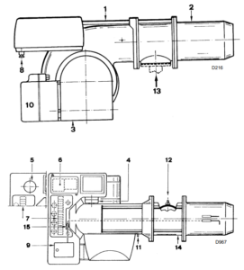
- Batang geser untuk membuka pembakar dan memeriksa kepala pembakaran
- Kepala pembakaran
- Katup gerbang udara tertutup hingga kehilangan panas berkurang.
- Sakelar tekanan udara
- Kapasitor
(Model GAS 3/2 – 4/2) - Pembuat kontak motor dan relai termal
(Model GAS 5/2 – 6/2 – 7/2) - Strip terminal
- Kabel yang bagus
(untuk sambungan listrik oleh pemasang) - Kotak kontrol dengan lampu pilot pengunci dan tombol reset pengunci
- Servomotor kontrol katup gerbang udara
(bukan untuk kode 20102494) - Titik uji tekanan kipas
- Titik uji tekanan gas ke selongsong
- Pipa masukan gas
- Selongsong
- Soket colokan pada kabel probe ionisasi
GASTRAIN
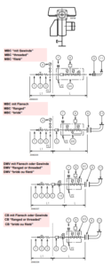
GAS TRAIN Approved according to standard EN 676 and provided separately from the burner.
KEY TO LAYOUT
- Gas input pipe
- Manual valve
- Vibration damping joint
- Pressure gauge with push-button cock
- Filter
- A Includes:
– Filter
– working valve
– safety valve
– pressure adjuster
6B Includes:
– working valve
– safety valve
– pressure adjuster
6C Includes:
– safety valve
– working valve
6D Includes:
– safety valve
– working valve - Minimum gas pressure switch
- Leak detection control, provided as an accessory or integrated, based on the gas
train code. In compliance with the EN 676
standard, the leak detection control is compulsory for burners with maximum outputs
over 1200 kW. - Gasket, for “flanged” versions only
- Pressure adjuster
- Train-Burner adaptor, supplied separately
P2 Upstream pressure of valves/adjuster
P3 Upstream pressure of the filter
L Gas train, supplied separately
L1 The responsibility of the installer
Note
See the accompanying instructions for the adjustment of the gas train.
To select the correct gas train model, refer to the
supplied “Burner-gas train combination” manual.
ELECTRICAL SYSTEM

installer-set
Use flexible cables according to regulation EN
60 335-1:
– if in PVC boot, use at least HO5 VV-F
– if in rubber boot, use at least H05 RR-F.
CABLE SECURING (A) – (B)
All cables to be connected to the burner terminal
strip 7)(A)p.8 should pass through fair leads
8)(A)p.8. The fair leads and precut holes can be
used in various ways. One example is given below:
GAS 5/2 – 6/2 – 7/2
1 – Three-phase power supply. . . . . . . Pg 21
2 – Single-phase power supply . . . . . . Pg 13,5
3 – Remote control device TR . . . . . . . Pg 13,5
4 – Remote control device TL. . . . . . . . Pg 13,5
5 – Gas valves . . . . . . . . . . . . . . . . . . . Pg 13,5
6 – Gas pressure switch or. . . . . . . . . . Pg 13,5
gas valve leak detection control device
7 – Fair lead fitting hole, if required . . . Pg 13,5
8 – Fair lead fitting hole, if required . . . Pg 11
To ensure that the IP 40 protection classification
is maintained, close all unused fair lead fitting
holes.
LAYOUT (C) – The GAS 3/2 – 4/2 Models electrical connection single-phase power supply
without leak detection control device.
LAYOUT (D) – The GAS 3/2 – 4/2 Models electrical connection single-phase power supply
with VPS leak detection control device.
Gas valve 8)-9)p. 18 leak detection control takes
place immediately before every burner starting.
KEY TO LAYOUTS (C) – (D)
IN – Manual burner stop switch
MB – Burner terminal strip
PG – Min. gas pressure switch
H – Remote lock-out signal
H1 – Remote lock-out signal of leak detection
control device
TR – High-low mode load control system:
controls operating stages 1 and 2.
If the burner is to be set up for single
stage operation, replace of remote control device TR with a jumper.
TL – Load limit remote control system:
shuts down the burner when the boiler
temperature or pressure reaches the
preset value.
TS – Safety load control system:
operates when TL is faulty
VR1 – Gas valve, stage 1
VR2 – Gas valve, stage 2
VS – Safety valve
XP – Plug for leak detection control device
Hubungi Kami
PT. INDIRA MITRA BOILER
Comments
No comment yet.